In this series, I will walk through the process of building a bowed string model using a digital waveguide. If you are not familiar with the technique, Julius O. Smith wrote a great book on the subject: Physical Audio Signal Processing. The particular model I will build can also be found in this book here.
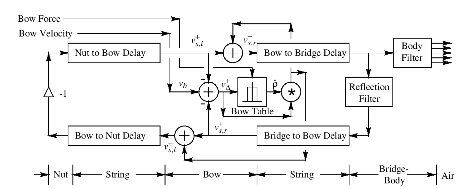
One possible way to implement this model would be to implement it exactly as presented using 4 distinct delay lines. This would work quite well for a static model, but since we want to be able to change the delay lines’ lengths in real-time, we will quickly run into some issues.
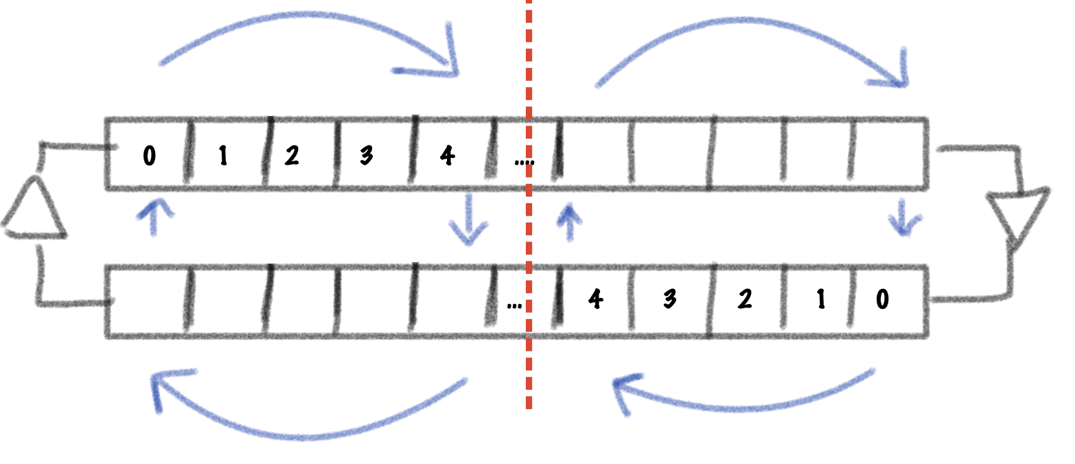
To understand, let’s look at a basic delay line implementation. The canonical delay line usually consists of a circular buffer and two pointers: one for reading and one for writing. Changing the delay length is as simple as changing the read pointer’s position. This looks something like this:
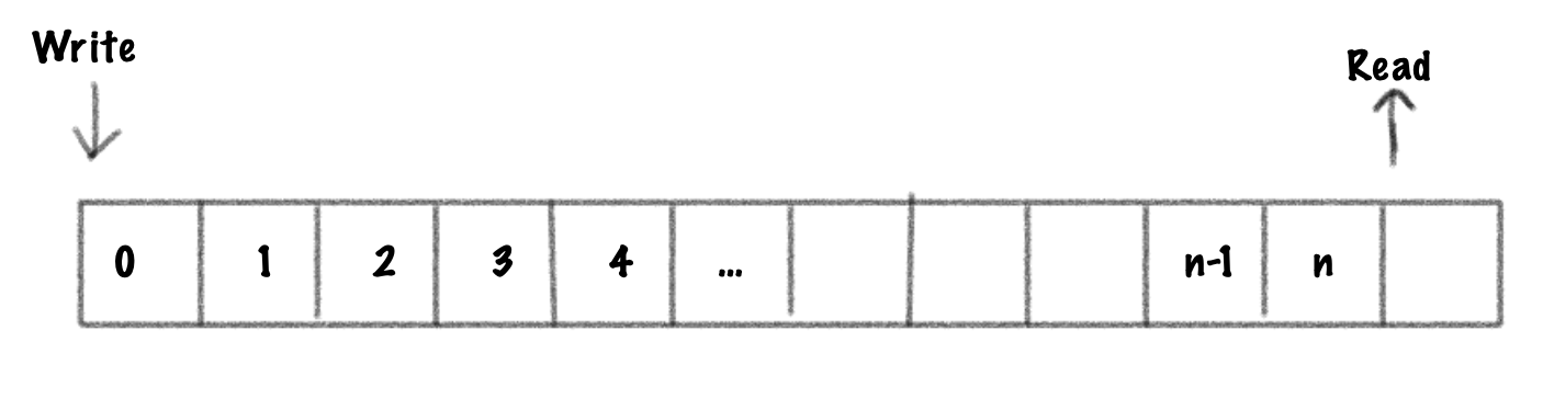
When the length of a delay line is changed in real-time, it is called a variable delay line. It is also possible to read between two sample points by doing an interpolated read. This would make the delay line a fractional delay line. Being able to read in between samples is important as it will allow us to smoothly change the delay length in real-time.
A simple waveguide can be implemented using two delay lines, one for the right traveling wave and one for the left traveling wave.
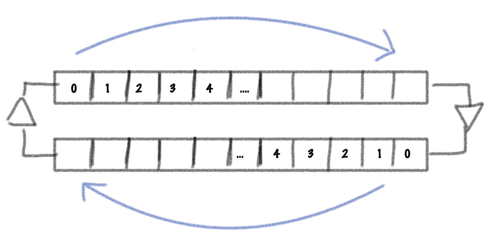
Notice how the delay lines are going in opposite directions. Now, if we were to change the waveguide length by reducing both delay line lengths this would look like this:
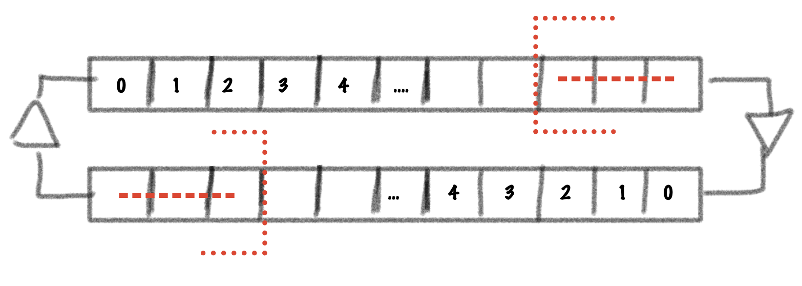
If the waveguide was modeling a string, we’ve now effectively removed a bit of the right traveling signal from the right end of the string and a bit of the left traveling signal from the left end of the string. This is physically impossible and can introduce discontinuities in the signal. Instead, what we want to achieve is something like this:
Notice how the size of the waveguide does not change and instead, a reflection point is introduced at some point on the string, effectively splitting the waveguide in two. This is attempting to simulate a finger pressing on the string.
On top of being able to read at an arbitrary fractional point on the delay line, we will also need to be able to write into the delay line at a fractional point. To do this, we can use an algorithm presented in Vesa Välimäki’s paper Discrete-Time Modeling of Acoustic Tubes Using Fractional Delay Filters. While Välimäki is describing a way to implement a scattering junction, we can use the same system to implement our reflection point by changing some of the coefficients. Instead of using an allpass filter to interpolate the signal I have opted to use a simple linear interpolator. Since we want to be able to vary the position of the junction in real-time, we would need to perform extra work to avoid the transient that would be introduced by using an allpass interpolation. A method to eliminate these transients is presented in this paper by Vesa Välimäki, Timo I. Laakso and Jonathan MacKenzie. A C++ implementation can be found in libdsp.
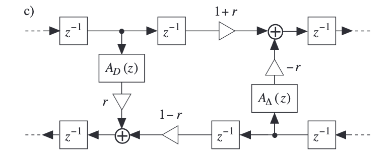
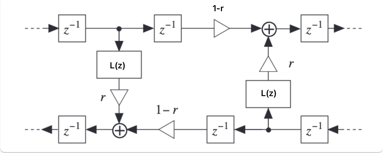
The resulting system is what we will now call a waveguide gate. The coefficient ‘r’ is what I will call the gate coefficient. With a value of 1, the gate is fully closed and all the energy is reflected. With a value of 0, the gate is fully open and all the energy is transmitted. With a value between 0 and 1, the gate is partially open and some of the energy is reflected and some is transmitted.
Here it is in action when the gate coefficient is set to 1:
By setting the gate coefficient to < 1, we can simulate a light press on the string which can result in harmonics based on the position of the gate:

Here are some audio examples of the gate in action using a waveguide with 200 samples of delay and a gate positioned in the middle of the string. A triangle pluck is used to excite the string.
Gate coefficient = 0 (open string):
Gate coefficient = 1 (full press):
Gate coefficient = 0.005 (The fundamental quickly morphs into the first harmonic):